
Lubrication Guide
LUBRICATION GUIDE
Lubrication System Design
A sound lubrication strategy is essential to keep all the moving components in your machinery operation running at their best to fight against friction.
Method for determining amount of lubricant required ‑
A useful guide is to calculate the frictional surface area (cm2) of the bearing and multiply by 0.0025 cm, this will give approximate volume of oil required to adequately lubricate over a one hour period for ‘Total Loss Systems’ and a one minute period for ‘Continuous Systems’. Where high speeds, loads, temperature, contamination etc. are encountered, allowance should be made by adding to the calculation as conditions demand.
Where more frequent operation is required, as for automatic ‘Total Loss’ systems, these quantities are inversely proportional to the operational frequency e.g.,
If icc is required for 1 hour then o.5 cc is required for 3o minutes, and so on.
Having determined the cc. of oil required per operation for each lubrication point, choose the nearest size of metering device (preferably above the calculated figure).
Add the individual requirements to give a total amount of oil to be dispensed by the pump.
Thickness and life of the Film of Lubricant
| Total Loss
Manual Automatic Recirculating Systems Continuous Flow |
Oil
0,0050cc/2-4h 0,0025cc/1h 0,025cc/min. |
Grease
0.0050cc/4-8h 0,0025cc/4h |
| To Calculate Requirements (cc)
Symbol Used – Unit of measurement cm. V = Required Volume – cc. A = Equivalent contact area – cm2 S = Thickness of lubricant film – cm Dp, = Pitch circle diameter (PCD) of gear – cm. Dp2 = Pitch circle diameter (PCD) of worm screw – cm. |
F = Width of pinion/band – cm.
D = Shaft diameter – cm. L1 = L. of support/guide – cm. L2 = Width of guide – cm. C = No. of crowns on bearings |
General Formula
V=A x S (equivalent area x thickness of film)
To Calculate Equivalent Area
| Roller Bearings | A = D2C | Large Dimension Gears | A = 2∏DpF |
| Plain Bearings | A = ∏DL1, | Screw/Wheel-mesh gears | A =∏ (Dp1 + Dp2)F |
| Slideways Gears | A = L1 L2
A =∏Dp1F |
Labyrinth rings | A = ∏DL130* |
* L1 should take into account the width of the gasket.
Pumps and Reservoirs
The selection of a pump for a system is governed by the total capacity of the metering units to be used. When using a piston type pump (volumetric system) the total capacity should not exceed 70% of the output of the pump stroke to ensure that the system operates efficiently. Allowances should also be made for expansion losses when using nylon tubing e.g., approximately icc per metre run of main lubrication line.
Reservoir capacity should be calculated by multiplying the total oil dispensed per cycle by the number of operations per working period according to Planned Maintenance Schedules.
A Comparison of the Viscosity of Lubricating Oils
Engler “Diagram” – mm2/S
The diagram shows variations in the figures for viscosity on two different scales (Engler values and mm”/S cSt values) plotted against temperature for some lubricating oils in common use.
Comparative curves are shown corresponding to many ISO VG grades of viscosity, as follows:
| ISO GRADE | CORRESPONDING TO |
| 3-10 | light oil |
| 32-100 | average machine oil |
| 320 | semi-thick oil |
| 1000 | thick oil |
It will be seen that the viscosity of ISO VG grade is equivalent to that of the lubricant expressed in cSt at a temperature of 40°C.
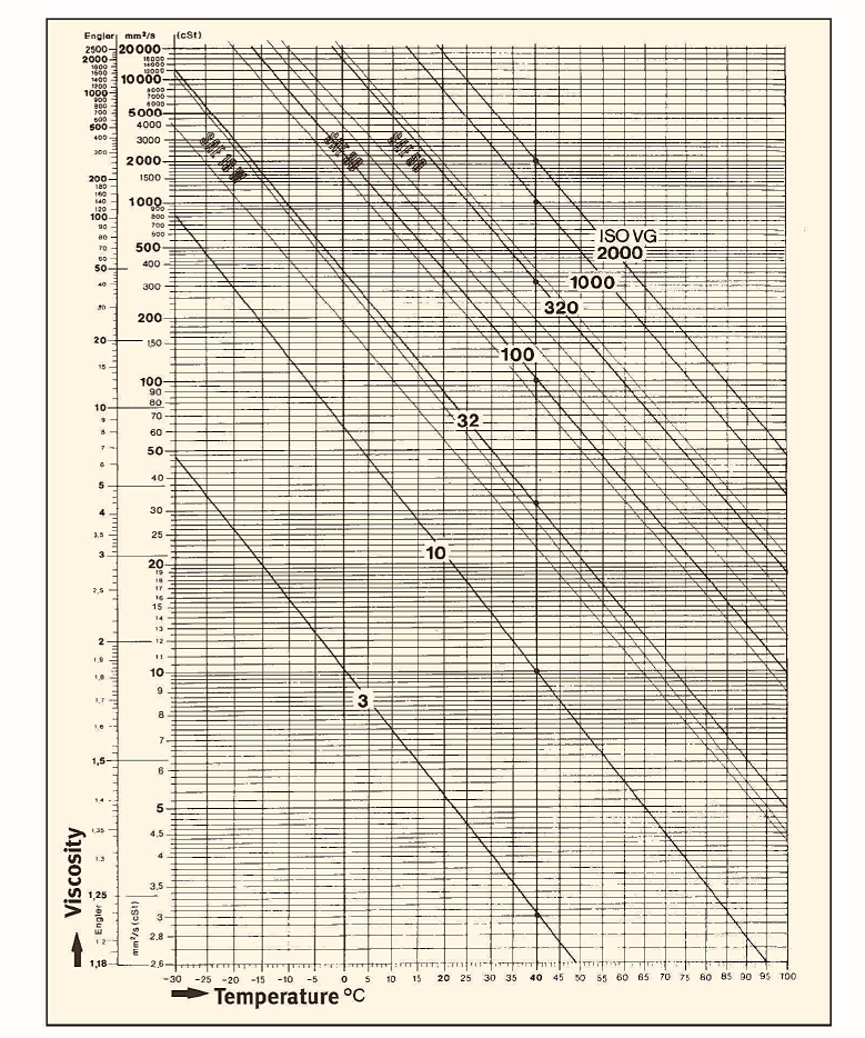
The diagram shows that oil viscosity is more affected by low temperature than high temperature.
The decision as to which type of lubricant to use also involves various considerations with regard to the structure of the machine, the parts which specifically requires lubricating and their characteristics which are not always mutually compatible. This often leads to a compromise solution representing the lowest common denominator of a whole range of requirements.
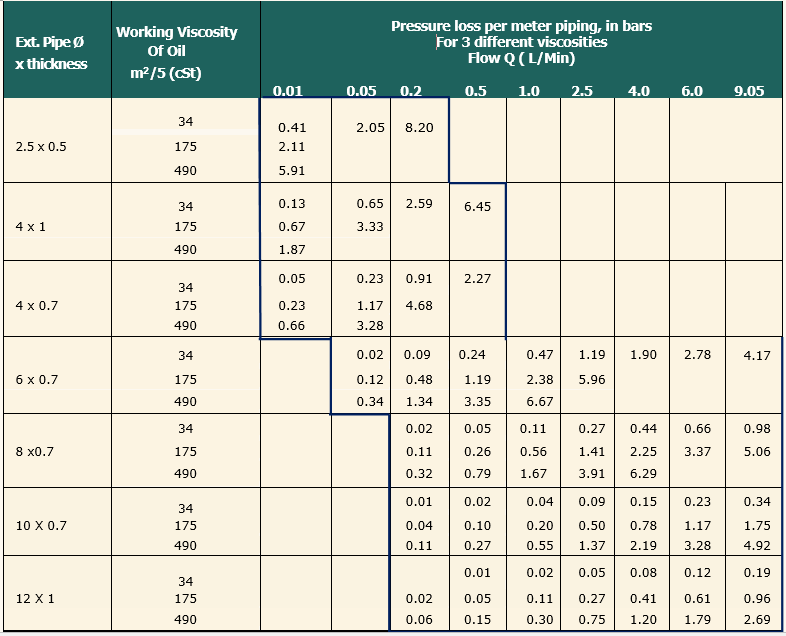
Pressure Loss For Lubricating Oils
Estimated pressure loss in piping when using lubricating mineral oils with viscosity: 34- 175- 490 cSt at 40°C.
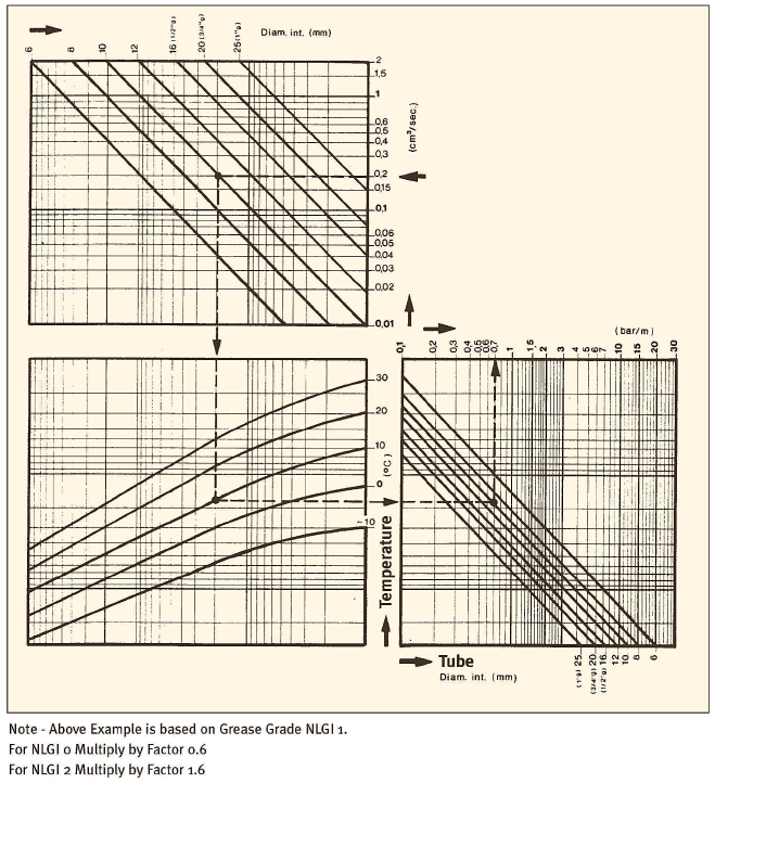
Pressure Loss in Pipework for Grease System
ESTIMATED LOSS USING NLGI 1 GRADE GREASE
Example
Volume 0.2 cc/sec.
Tube Bore 10 mm
Temperature 10°C
Grade of Grease ASTM (NLGI)
Pressure Loss = 0.7 bar/m
| Understanding Lubrication Maintenance Cost |  |
| Oil Lubricant makes up less than 1% of operating cost | Lubricant influence more than 50% of maintenance cost | LHL lubricating system reduces oil lubricant consumption by 90% as well help to reduce maintenance cost. |
 |
 |
 |
 |
General Information Viscosity |